


Introduction#
This report is intended to outline the most common and important features of the maps and/or charts provided in a select group of VFR EFBs on the market. The intent is to provide Navigraph with the necessary details to recreate such an application as a compliment to their current IFR-focused charts.
Goals#
- Create a list of the most commonly occurring features (MEL)
- Order the list in a way that highlights the options with high ROI
Specifications#
This report will be divided into different sections. This will be done by categorizing the features into small groups of features, and each section will contain a separate, cross-product analysis of the features that fall under it.
-
Base layer
The bottom layer of the map. Consists of basic map features that are available even in non-aviation related maps.
-
Objects layer
A layer of additional features, mostly consisting of obstacles and points of interest.
-
Airspace layer (Aeronautical)
The most important layer in the stack. Contains an often configurable amount of airspaces, restriction zones and noise abatement zones.
-
Navaid layer (Aeronautical)
A layer containing radio navaids like VOR/DMEs along with the ability to show airways from the IFR enroute charts as an overlay.
-
Procedures layer (Aeronautical)
A somewhat advanced layer containing VFR-specific procedures like CTR entry points, holding points and sometimes procedures that local clubs/airfields may have agreed on.
1. Base layer#
The base layer is responsible for orienting the user by showing features that anyone can relate to. Most people can orient themselves roughly by looking at a map with only lakes, rivers and coastlines rendered, but for a more precise orientation other reference points are required.

1.1 Differences and common features between the products#
Please note that the below is in reference to the product’s initial, non-customized look. Missing features like roads, highways etc. can often be turned on in the settings.
| Feature | SkyDemon | ForeFlight | Skyvector | LittleNavMap |
|---|---|---|---|---|
| Map projection | 2D | 3D (Spherical) | 2D | 2D |
| Towns & Cities | Most | All | Most | All |
| Powerlines | Visible | Configurable | USA only | OSM |
| Railroads | Configurable | Adaptive | USA only | OSM |
| Roads | Configurable | Adaptive | Highways | OSM |
| Water features | Detailed | Detailed | Bodies only | OSM |
| Terrain | Configurable | Configurable | Detailed | OSM |
| Trees/Forest | ? | Detailed | Less detailed | OSM |
2. Objects layer#
The objects layer contains additional map features that either helps with recognizing an area or aids aviators not to put themselves or their aircraft in immediate danger. Antennas, windmills, tower cranes, high buildings, churches/castles and towers are all relevant. Objects and obstacles like these tend to serve the VFR aviator well when planning their trip, as they are easy to spot even from a certain height and distance because of their elevation over the ground.

2.1 Differences and common features between the products#
Please note that the below is in reference to the product’s initial, non-customized look. Missing features can sometimes be turned on in settings.
| Feature | SkyDemon | ForeFlight | Skyvector | LittleNavMap |
|---|---|---|---|---|
| Chimneys & Antennas | Symbol + Info | Generic + Details | Generic* | None |
| Churches | Symbol + Info | Generic + Details | Generic* | None |
| Windmills | Symbol + Info | Symbol + Info | USA only | None |
| Sites | Symbol + Info | None | USA only | None |
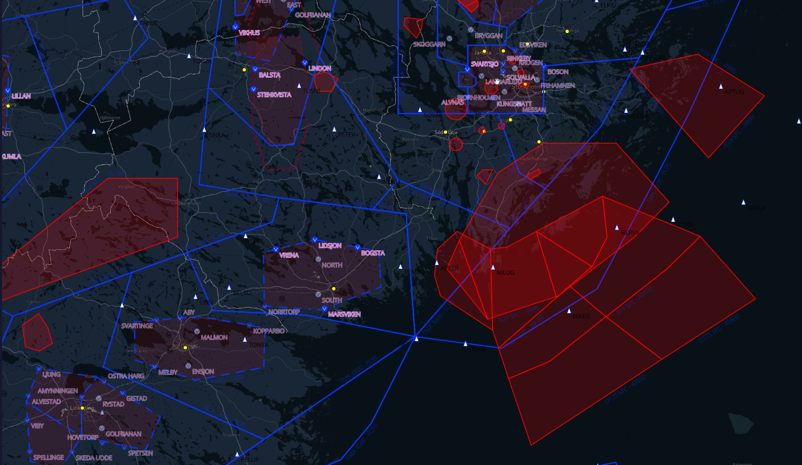
3. Airspace layer#
The airspace layer is the most important of all layers. This layer prevents aviators from doing airspace infringements, and guides those who want to do so intentionally by presenting intuitive information. The main goal is to aid the aviator when visualizing the airspace, not just in reference to its horizontal spread but also on the vertical. This makes it easier for the aviator to fully grasp the constraints of the “box” that represents the airspace.
In addition to the usual airspaces, temporary and sometimes permanent but adaptive airspaces like restriction zones and noise abatement zones need to be presented to assure a safe flight. These need to be intuitively drawn in a way that draws the aviators attention, preferably before flying through the airspace.

3.1 Differences and common features between the products#
| Feature | SkyDemon | ForeFlight | Skyvector | LittleNavMap |
|---|---|---|---|---|
| Airspace altitudes | Ident + range | Ident + range | Ident + range (USA) | Info on hover |
| Airspace (Class) | All | All | All (USA) | All |
| Restriction zones | Ident + Range | Ident + Range | USA Only, Range | Info on hover |
4. Navaid layer#
The navaid layer includes VOR/DMEs, NDBs, fixes and airway reporting points.
4.1 Types#
4.1.1 Radio navigation aids#
These enable the user to plan their route using radio beacons, which in turn provides the user with the ability to fly the planned trip without the use of a map with live position tracking. Instead, the software can print a navlog that states bearings/radials and distances from said navaids.
4.1.2 Airway reporting points#
Airway reporting points like NOSLI, ARS, MAXIV etc may not be frequently used by VFR pilots, but they do come in handy when flying routes that do not have any radio navaids and/or visual landmarks. A good example would be flying over large patches of open, perhaps international waters. Then airway reporting points can be utilized, provided that the aircraft is equipped with a GPS.

4.2 Differences and common features between the products#
| Feature | SkyDemon | ForeFlight | Skyvector | LittleNavMap |
|---|---|---|---|---|
| Radio navaids | Ident + rose | Ident + range | Ident + range USA | Id + Freq + Rose |
| Airway points | Generic* + id | Unique + id | None | Generic* + id |
| Airspace (Class) | A, E, B, C, D, G | A, E, B, C, D, G | A, E, B, C, D, G | A, E, B, C, D, G |
| Restriction zones | Ident + Range | Ident + Rose | Id, name, freq (USA) | Info on hover |
5. Procedures layer#
A somewhat advanced layer containing VFR-specific procedures like CTR (Visual) reporting points, holding points and sometimes procedures that is either published in the AIP (see ESSB for an example) or that local clubs/airfields may have agreed on together.
5.1 Types#
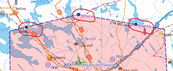
5.1.1 Visual reporting points#
Visual reporting points are used by VFR traffic when entering controlled airspace. To ensure the safety of flight operations, ATC requires VFR traffic to enter at specific points along the edge of the airspace. Upon entry, the traffic might either be given a clearance to land or get sent to a VFR holding point. These are located out of the way of incoming heavy traffic, and are usually located on top of visually identifiable objects/landmarks.
5.1.2 Holding points#
Holding points are published areas in the vicinity of medium to large airports where VFR traffic is routed in case of incoming IFR/heavy traffic.

5.1.3 Flight paths#
Also published in the API most times, the flight paths depicted below are procedures that resemble STARS and SIDS for IFR traffic. These are not very common and can be found at/around airports surrounded by sensitive areas which need to be avoided.

5.2 Differences and common features between the products#
| Feature | SkyDemon | ForeFlight | Skyvector | LittleNavMap |
|---|---|---|---|---|
| Reporting points | Ident | Ident | None | None |
| Holding points | Yes | Yes | None | None |
| Flight paths | Some AD | Some AD | (Generated)** | None |
The fact that Foreflight is able to produce the flight paths automatically is cool and all, but for airports like ESSB (pictured above), flight paths are custom by nature and cannot possibly be automatically rendered without compromises.